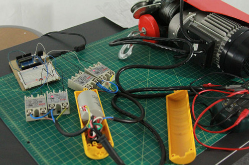
R2D2 electronic set up
R2D2 electronic set up - Pi + Arduinos — Built @yesyesno
R2D2 Remote Control app built by Jamie Kosoy with Node JS
R2D2 in progress
Work in Progress
R2D2 built process
Work in Progress.
The Making of R2D2 for Stacey's starwar wedding 2013
Work in Progress:
Behind the scene stop motion animation
[Documentation] Revised: Hacking an AC motor with Arduino
* updates: The instructables is online now by our very own Marcela Godoy :
http://www.instructables.com/id/How-to-hack-an-Electric-Hoist-AC-motor/
We were hired to do a small hacking project for a trade show. Basically we want to be able to control the direction of the AC motor and to launch timed actions.
The AC motor that we’re giving has a built-in motor controller, a capacitor, and a pendent switch, that allows manually adjusting the directions.
We are able to control the direction of an AC motor from arduino uno, and still allow any manual control from the pendent switch (when arduino is not running).
We figured out a few things in this project which will probably be helpful to point out for anyone who attempt to do so on one’s own:
1. The wiring of the motor controller and its switch.
2. The circuit for interfacing AC motor with 5V logic using Solid State Relays and an Arduino Uno. The Arduino control it in both direction using two PWM output.
3. When we control the AC motors with the solid state relays, the relays dont discharged the capacitor. So when the capacitor is not being discharged, the motor will go on the same direction as the charge. The inclusion of a resistor between the both terminals of the capacitor will help discharging the capacitor when the motor is not operating.
This is a place holder for a video of the operation when we set it up at the space tomorrow.
=============================>
Materials you’ll need:
- http://www.harborfreight.com/1100-lb-capacity-electric-hoist-93251.html // datasheet can be found here. We started with 880 lb capacity and end up using 1100 lb. The only difference in this circuit is the value of the resistors
- Amico 250V 25A SSR-25DA Temperature Control Solid State Relay. We need 4 units.
- 200K ohm resistor, you’ll need one for each capacitor
- 14 AWG cable to handle AC current
- Arduino Uno
- small breadboard
=============================>
A. Wiring the Solid State Relay from Pendent switch
Diagram:
A-1
Our wiring looks like this:
B. The Charge will start at its maximum value which is 200K with this capacitor. We add a 200K Ohm Resistor on both leads of the Capacitor. There are two capacitors in parallel for the 1100 lb motor. So the resistors are hook up in parallel in this image.
* Notes: To calculate the discharge time. We have 80 uf capacitors and we are discharging with a 200k resistor The time constant is 16 seconds. T=R * C Where, R is in Ω’s and C in Farads.
D.
Happy Hacking
=============================>
C. Try this code for your arduino to control the direction with a 25% duty cycle
You can download the code from github
https://github.com/openMolmol/hack-acmotor-with-relay-and-arduino
=============================>
[Documentation] AC Motor Hacking
We are spending the day trying to hack an AC motor for use at a trade show. We do not need to control the speed of the motor, just direction.
We are running into trouble today controlling both directions. We were able to control just one direction before with two relays. This time, we added two more relays and the motor stops working on either direction. The problem we’re trying to solve today is to control both directions at its full speed.
Here are some steps that we took and image reference:
————————————————————————->
We were able to control the SSRs with arduino and the code below,
You can see from the video
We are using this motor:
http://www.harborfreight.com/880-lb-electric-hoist-44006.html
which has a 25% duty cycle.
It has a built-in motor controller, and the motor comes with a pendent switch to control the direction.
We are using four of these
Amico 250V 25A SSR-25DA Temperature Control Solid State Relay
to hack the motor pendent switch.
We are using the datasheet from the motor’s manufacturer.
Marcela and Eric Rosenthal colored it and drew the connections from the pendent switch to Solid State Relays and an Arduino:
The wiring look like this:
Here's the code that we're using:
————————————————————————->
//Another experimental code that we’re working on add a equation for the 25% duty cycle, still it’s not working with the motors but it can controls the solid state relays
int SSRPin1 = 5; // motor forward
int SSRPin2 = 6; // motor backward
//int val = 200; // variable to store the read value
void motorForward();
void motorBackward();
int secondsForLift; // how long should the lift be in seconds
float pctLiftToTotalTime; // duty cycle — how much one cycle is lift = 25% = 2.5 second lifting, 7.5 seconds waiting
int totalCycle; // lift + rest = one full cycle.
// pctLiftToTotalTime = pct of x’s per total: xxxx—— = 50%
// totalCycle = how long is the whole sequence: xxxx—— = 8…
//————————————————————————————————-
void setup() {
Serial.begin(9600);
pinMode(SSRPin1, OUTPUT);
pinMode(SSRPin2, OUTPUT);
secondsForLift = 5; // one second
pctLiftToTotalTime = 0.25; // 25% duty cycle
totalCycle = secondsForLift * (1 / pctLiftToTotalTime);
// 0.25X = 60 (sec) X = 60 (second) /25%
}
//————————————————————————————————-
void motorStop(){
digitalWrite (SSRPin1, LOW);
digitalWrite (SSRPin2, LOW);
Serial.println(“stopped”);
}
//————————————————————————————————-
void motorForward() {
analogWrite (SSRPin1, 253);
digitalWrite (SSRPin1, HIGH);
digitalWrite (SSRPin2, LOW);
Serial.println(“forward”);
}
//————————————————————————————————-
void motorBackward() {
analogWrite(SSRPin2, 253);
digitalWrite(SSRPin1, LOW);
digitalWrite(SSRPin2, HIGH);
Serial.println(“backward”);
}
//————————————————————————————————-
void loop(){
unsigned long millisecond = millis(); // todo: check if this wraps over
Serial.println(millisecond);
unsigned long totalCycleInMillis = totalCycle * 1000;
unsigned long whichCycle = millisecond / totalCycleInMillis; // which cycle is a counter that keeps increading (0,1,2,3…)
boolean bForward = whichCycle % 2 == 0 ? true : false; // we are going forward if the counter is even….
boolean bMoving = (millisecond % totalCycleInMillis < secondsForLift*1000) ? true : false;
// bMoving = are we in or out of duty cycle
// bForward = are we going forwards or backwards
if (bForward && bMoving) motorForward();
if (!bForward && bMoving) motorBackward();
if (!bMoving) motorStop();
}
}other links:
The code we were using were based on Computergeek’s instructables:


